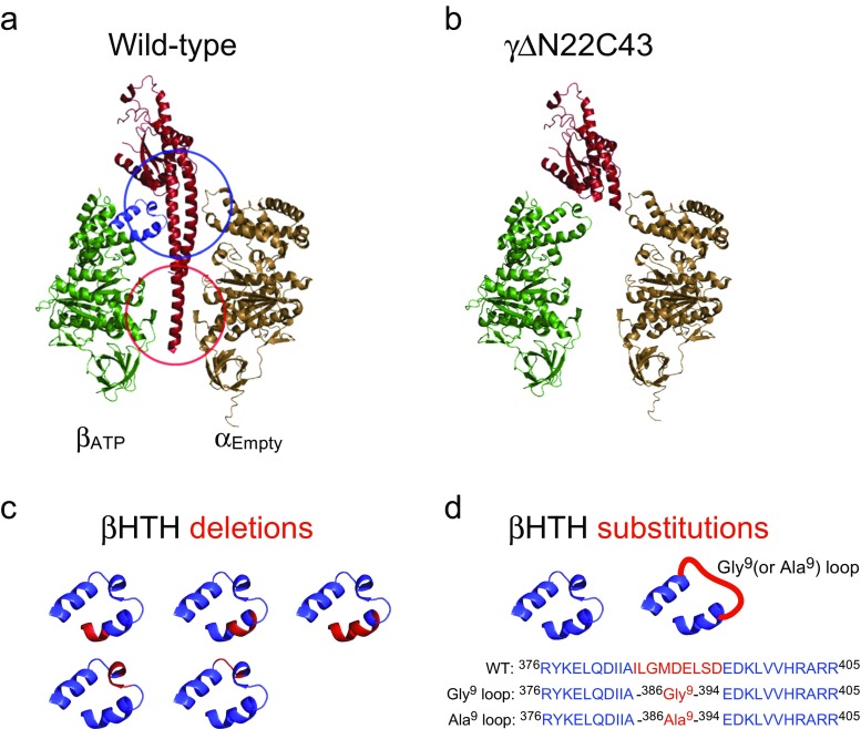
Fig. 5.
Stator–rotor interactions within F1. a αEmpty–βATP pair and the γ subunit are shown as cartoon representation (PDB ID: 1E79). The blue and red circles indicate the orifice and sleeve regions in the α3β3-ring, respectively, at which the γ subunit is held. The helix-turn-helix (HTH) structure of the β subunit forming the main interface of the stator orifice is colored blue. b The structure of axle-less mutant γΔN22C43 (Furuike et al. 2008). The 22 residues of the N-terminal helix and the 43 residues of the C-terminal helix in the γ subunit are deleted. c The positions of deletion in the HTH structure are shown in red (Usukura et al. 2012). d All residues of the HTH in contact with the γ subunit are substituted with glycine or alanine (red region) (Tanigawara et al. 2012)

