
FIGURE 2.
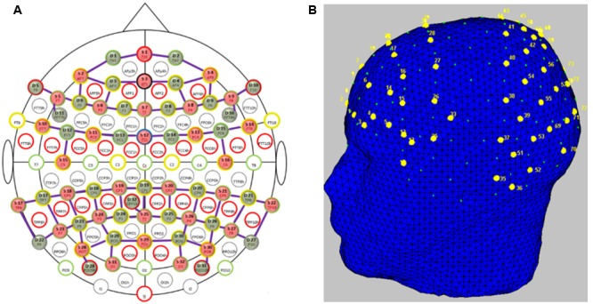
Functional near-infrared spectroscopy probe placement. (A) Topologic layout of the emitters (red), detectors (green) and the fNIRS channels (purple) on a standard 10–20 EEG system. Figure reproduced from NIRStar software with permission from NIRx Medical Technologies, LLC, USA. (B) FNIRS channels (labeled in yellow) superimposed onto the head model depicting coverage over the frontal and parietal and temporo-occipital areas. Figure generated using nirsLAB toolbox1.