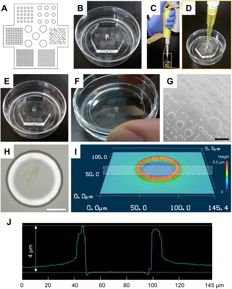
Fig 2. Preparation of agarose micro-wall array.
(A) Pattern design. (B) Polydimethylsiloxane (PDMS) mold with the designed pattern was placed on a poly-L-lysine coated glass bottom dish. (C) Application of agarose solution to degassed PDMS mold. (D) Few-hundred-μL-agarose solution was applied from the center hole of degassed PDMS mold. (E) The internal space of PDMS mold was gradually filled with agarose solution without any external pumping. (F) The agarose micro-wall array recovered on the glass surface. (G) Microphotograph of a part of agarose micro-wall array with variety features. Black bar indicates 800 μm. (H, I, and J) Microphotograph, three-dimensional view, and cross-sectional profile of the smallest feature of agarose micro wall. White rectangle in (I) indicates the area of cross-sectional profile (J). White bar indicates 20 μm.

