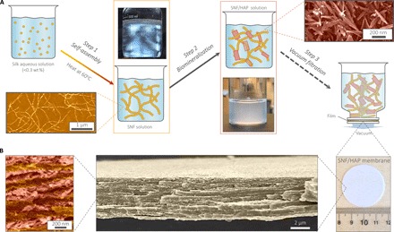
Fig. 2. The pathway to fabricate the SNF/HAP membranes and visualization of typical multilayer structures formed.

(A) Schematic of the preparation steps of SNF/HAP membranes. Step 1: Silk was assembled to SNFs in aqueous solution. The bottom image in the first row is an atomic force microscopy (AFM) image of SNFs; the top image in the second row is the SNF solution under polarized light, indicating the presence of a nematic phase of SNFs. Step 2: The SNFs were used as templates to induce the growth of HAP nanocrystals. The bottom image in the third row is an image of SNF/HAP solution; the top image in the fourth row is a scanning electron microscopy (SEM) image of biomineralized HAP nanocrystals. Step 3: SNF/HAP dispersions were assembled into membranes via vacuum filtration. (B) Multilayer structures of the membranes. The third image is an SNF/HAP membrane with a thickness of 4 μm. This membrane was directly moved from the supporting substrate after filtration of the SNF/HAP dispersion in a process that took 9 s. The second image is the cross-sectional SEM image of SNF/HAP membrane, which shows nacre-like, highly ordered multilayer structures. The first image is the high-resolution cross-sectional SEM of an SNF/HAP membrane. The clear SNF- and HAP-rich layers can be observed. False color was used in AFM and SEM images.
