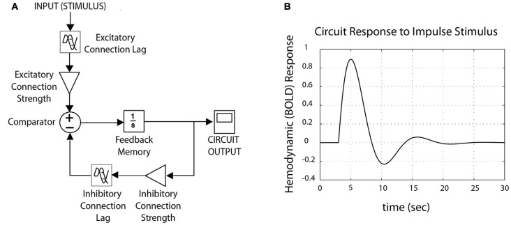
Figure 2.
Schematic control system, tuned for fMRI data. (A) A schematic control system is structured as a negative feedback loop, with both excitatory and inhibitory components. Circuit-wide dynamics change as a function of lag and connection strength (“connectivity”) between nodes, resulting from variation in synaptic plasticity and/or neurotransmitter/receptor density. (B) Outputs from the model produce waveforms comparable to canonical hemodynamic response function typical for fMRI (here, shown for impulse stimulus).

