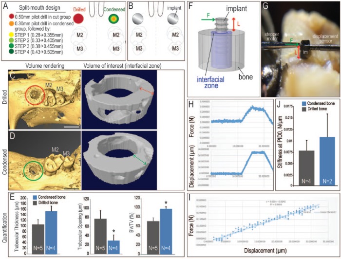
Figure 1.
Condensation-induced changes in bone microarchitecture. (A) Schematic of the experiment, where a split-mouth design was employed to test the effects of bone condensation prior to implant placement. In all animals, the maxillary first molar was extracted, and after 3 wk of healing, 0.50-mm osteotomies were created. In the drilled group, this was accomplished by drilling the bone (red circle). In the condensed bone group, 4 osteotomes were used in succession (green circles, see Methods). (B) A 0.62-mm titanium implant was then placed in the prepared osteotomies of both groups. (C) Immediately after osteotomy preparation, a subset of animals in the drilled bone group were sacrificed and examined by micro–computed tomography. The volume of interest (indicated with a red circle) was examined by volume rendering and by cross-sectional analysis, focusing on a 300-µm-wide annulus of peri-implant bone. (D) In the condensed bone group, the volume of interest (indicated with a green circle) was analyzed in the same manner. (E) Quantification of trabecular thickness, trabecular spacing, and bone volume/total volume (BV/TV). *P < 0.05. (F) Experimental system used to evaluate lateral stability of implants placed in osteotomies created by drilling or condensing. (G) A stepper motor delivered a defined displacement (Δx) at a specified height along the implant (L), and the resulting force (F) was recorded. (H) Representative recordings of force (measured in newtons) and resulting displacement (measured in microns) from a trial run. (I) Primary stability was equivalent regardless of whether the implant was placed into an osteotomy created by drilling (gray) or condensing (blue) the bone. (J) The slope of the F/Δx plot was calculated from the linear portion of the trace. PID, postimplant day. Scale bars: C, D = 1 mm.

