
Figure 6. Structure of the AP C3 convertase with bound FPc.
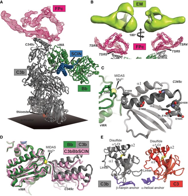
- Crystal structure of the SCIN‐stabilized C3bBbPc complex. The FPc‐containing electron density map is a real space twofold averaged 2mFo‐DFc map contoured at 0.8 σ containing no model information concerning FPc.
- C3b and Bb seen from a FPc perspective. Residues with side chains displayed are facing the FPc‐containing density and are therefore putative interaction partners.
- Comparison of the SCIN‐stabilized C3bBbPc (gray and green, this study) and C3bBb complexes (pink, RCSB entry 2WIN) (Rooijakkers et al, 2009). Binding of FPc causes a significant rotation of the C3b C345c domain relative to Bb.
- Comparison of the anchor region (blue) preceding the C345c domain in the SCIN‐stabilized C3bBbPc complex (left) and in native C3 (right, RCSB entry 2A73) (Janssen et al, 2005). The α‐helical conformation is found only in C3 and in C3b bound to FH or MCP. The β‐hairpin is present in all other known structures of C3b and C3c.