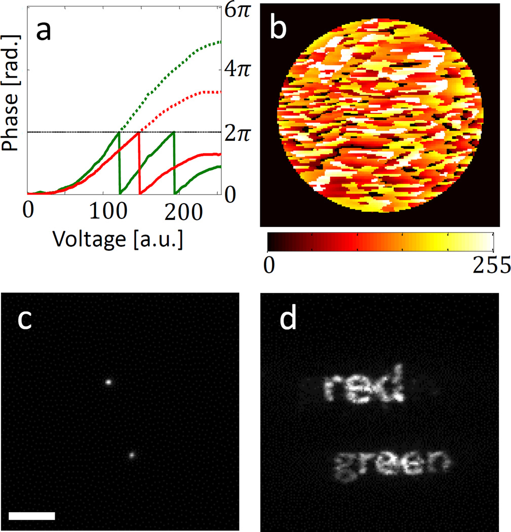
Figure 1. Dual-colour mask SLM implementation.
a, A LC-SLM pixel’s phase response as a function of input voltage for two wavelengths: 559 nm (green) and 699 nm (red). The dotted lines show unwrapped phases. b, Input “red-green” LC-SLM voltage pattern (8-bit grey scale). c, Two fluorescent microspheres (red and green) imaged with the LC-SLM off. d, The same two microspheres imaged with the pattern on. Scale bar = 5 µm.

