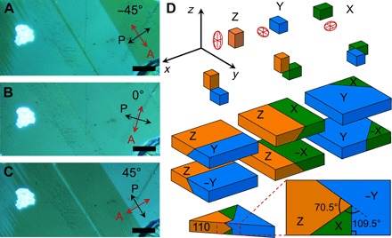
Fig. 1. Polarized light optical images and domain configurations in a MAPbI3 single crystal (sample C).

(A to C) Reflection-mode polarized optical micrographs (crossed Nicols) showing contrast reversal of domain groups as a function of sample rotation relative to the polarizer-analyzer (P-A) pair. At 0° relative angle, the domain groups are indistinguishable, and, at 45° and −45°, the domain contrast is maximum; that is, θe = 90°. The red and black arrows indicate the analyzer orientation and polarizer orientation, respectively. The light intensity of a bright dust particle is insensitive to the sample rotation. Scale bars, 5 μm. (D) Permissible domains of the MAPbI3 tetrahedral phase. At the cubic-to-tetrahedral transition, the tetrahedral unit cell can form with the c axis aligned along any of the three axes (x, y, and z) of the parental cubic phase, leading to three possible configurations (X, Y, and Z). To preserve crystal integrity, the a axes of different domains must coincide (32), leading to six possible domain orientations that are characterized by domain walls intercepting at 0°, 90°, or 45° in the principal planes of the parental phase and at ≈70° and ≈110° in the (110) plane.
