
Fig. 2. Writing current effect on the spin signal.
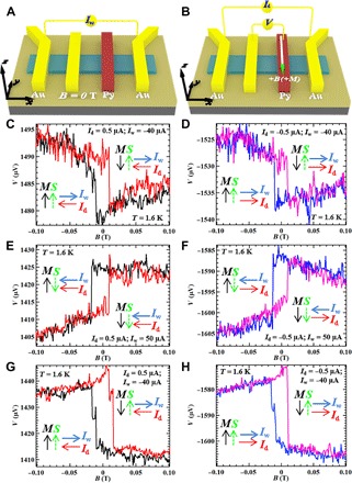
(A and B) Schematic four-terminal device structures and measurement setups for writing current and spin potentiometry. (C to H) Voltage detected by the FM contact as a function of in-plane magnetic field measured on device B at the relatively small Id of 0.5 μA (C, E, and G) and −0.5 μA (D, F, and H) after applying a large Iw of −40 μA for 2 hours (C and D), 50 μA for 0.5 hours (E and F), and −40 μA for 3 hours (G and H). The trend of the B field–induced voltage change, which measures the direction of the channel spin polarization, is independent of the relatively small Id but is set by the direction of the large Iw (applied at B = 0 T and before the spin potentiometric measurement). The directions of Id, Iw, channel spin polarization S as determined by the spin signal, and Py magnetization M are labeled by the corresponding arrows. All the measurements are performed at T = 1.6 K.