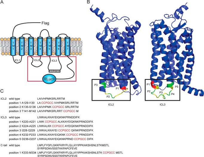
FIGURE 1.
Sensor design and location. A, schematic of all FlAsHwalk-tagged AT1R sensors that also carry an N-terminal FLAG epitope for immunodetection and a modified Renilla luciferase fused to the C terminus of the receptor. The red square defines regions of the receptor containing the FlAsH binding sequence. B, 3D view of biosensor location in AT1R. Shown is a ribbon representation of the human AT1 receptor structure generated using the web-based application I-TASSER (51) based on the recently acquired crystal structure of the human AT1R bound to the antagonist ZD7155 (Protein Data Bank code 4YAY). Corresponding intracellular loops are shown in yellow, and FlAsH insertion positions are in green. The FlAsH insertion at the C-tail is not shown because the structure of this receptor domain was not resolved. Positions marked in red show sensors that were defective in either surface trafficking or signaling. Left, ICL2 sensors; right, ICL3 sensors. C, amino acid sequence of the different intracellular receptor regions targeted by the FlAsHwalk strategy (black lettering) and their corresponding sites of FlAsH binding sequence (red).

