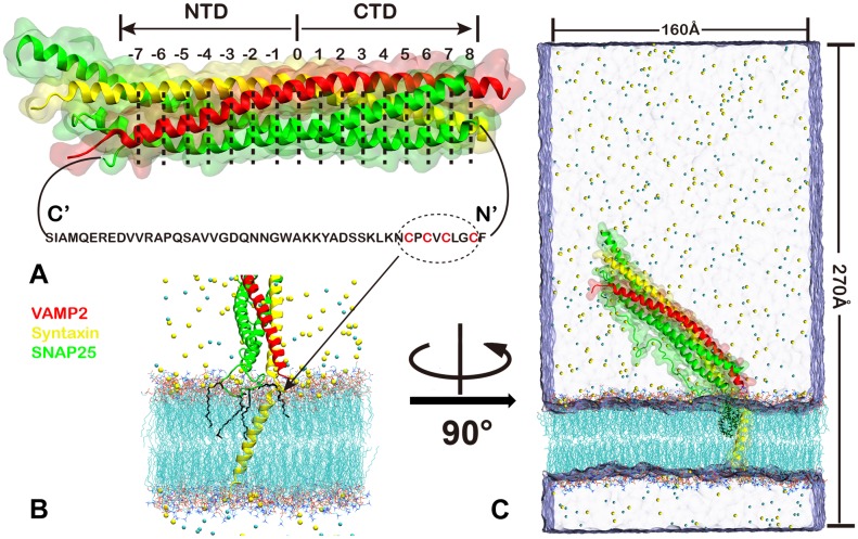
Fig 1. SNARE complex and the simulation setup.
(A)Schematic of ternary SNARE four helix bundle with Syntaxin(yellow), VAMP2(red), SNAP25(green). The notation of SNARE layers is indicated. The sequence of linker loop of SNAP25 is shown, 4 palmitoylated cysteines anchored to the membrane were shown in red. (B)Assembly of SNARE complex with the membrane, with the palmitoylated cysteines on SNAP25 highlighted. (C)The initial simulaiton system. The SNARE core domain is placed ~ 40° reletive to the membrane.

