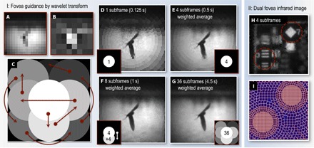
Fig. 5. Detail estimation and infrared dual fovea reconstruction.

(A to C) Fovea guidance by wavelet transform. (A) The fovea trajectory is determined by first measuring a blip-frame. A single-tier Haar wavelet transform is then performed on (A) to produce an edge contrast map (B) from which the fovea trajectory is then determined (for details, see Materials and Methods). (C) Map of the fovea trajectory within the field of view. Brighter regions indicate areas that the fovea visits earlier. Arrows show the trajectory of the fovea. (D to G) Image reconstructions after sampling the scene with various numbers of subframes and fovea positions. In this example, the fovea trajectory determined by the wavelet transform samples most of the detail in the scene after eight subframes. This is 50% of the time required to sample the entire field of view at the same resolution as the center has been sampled here. (H and I) Dual fovea infrared image. (H) Weighted average of four subframes (1368 cells per subframe; frame rate, 6 Hz), each having two fovea. (I) Cell grid of one of the subframes.
