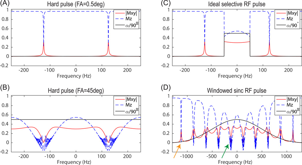
Figure 1.
bSSFP frequency response with small flip angle (0.5°) hard pulse (A), large flip angle (45°) hard pulse (B), ideal selective RF pulse (passband/stopband flip angle = 45°/0.5°) (C), and a windowed sinc RF pulse (flip angle = 45°, duration = 2ms, bandwidth = 1kHz). “|Mxy|” is the averaged transverse magnetization over all echoes during transient state, “Mz” is the longitudinal magnetization after the last echo, “α/90°” is RF pulse excitation flip angle divided by 90°. Simulation parameters included: number of echoes = 256, TR = 4ms, T1 = 40s, T2 = 300ms, and linear ramp preparation pulse (N = 5).

