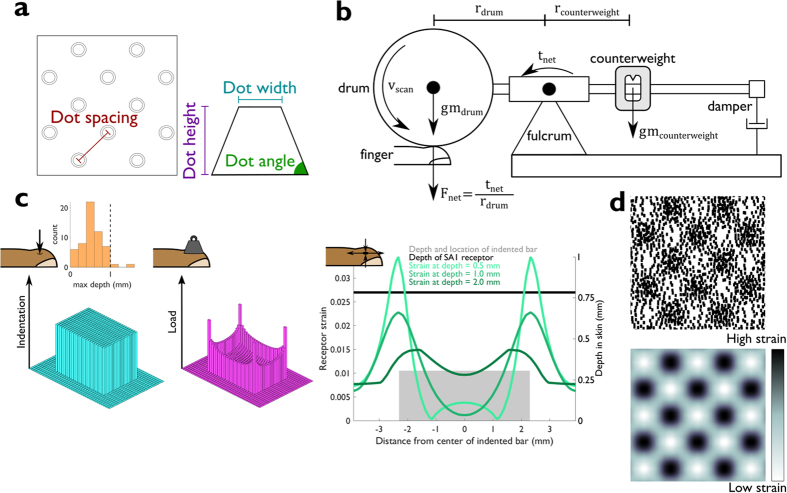
Figure 1. Methods.
(a) Top view of an embossed dot pattern and side view of an individual dot. Dot patterns can be described with just four parameters. (b) Diagram of apparatus used to scan dot patterns across the skin, adapted from (Johnson & Lamb 1981). The drum is lowered onto the fingertip and spins with velocity vscan to scan a dot pattern mounted to its circumference across the finger. The force, Fnet, with which the drum contacts the fingertip is a function of the net torque, tnet, at the fulcrum of the lever, which is adjusted by moving a counterweight at the other end of the fulcrum. A damper ensures that sharp jolts in contact force or drum displacement are kept to a minimum. (c) Schematic of the skin mechanics model (adapted from Sripati et al.9). Left: Pattern of skin indentations. Inset depicts the distribution of maximum indentation depths produced across all textures. Note that depths are not identical to the distribution of actual heights as some dots do not indent the skin all the way, particularly when dots are relatively dense. Middle: Pattern of forces exerted on the skin by the pattern. Edges and corners tend to bear most of the load. Right: Cross section of the strains produced by the indented bar experienced by receptors at different depths in the skin. The spatial distribution of forces changes as they propagate through the tissue, which results in depth-dependent patterns of strain. (d) Spatial event plots (SEPs). Top: Spike raster of a typical SA1 afferent aligned with the locations of the dots in panel a. Bottom: Profile of simulated strains caused by the same dot pattern. Locations of greatest strains align with the locations of the dots in the pattern (see (a), Left). Strains are used as a proxy for SA1 firing rates.

