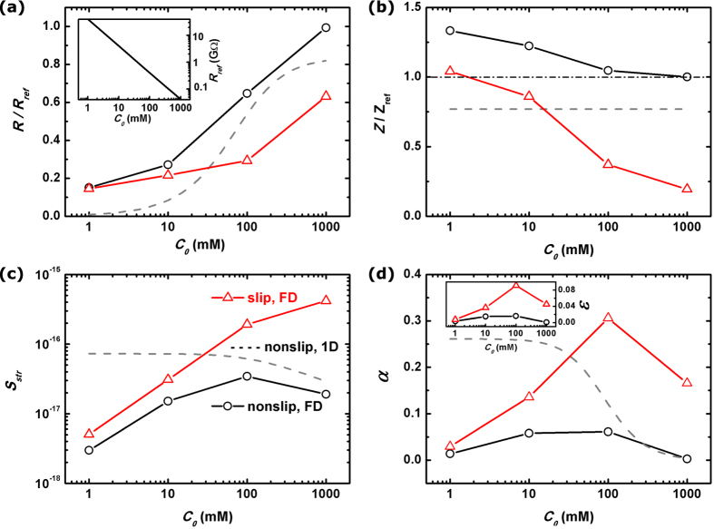
Figure 7. Nanopore figure of merit.
The calculated electrical resistance R (a), fluidic impedance Z (b), streaming conductance Sstr (c) and figure of merit α (d) of a nanopore system with Rp = 5 nm and Lp = 40 nm. The solid lines with round symbols stand for our full-dimensional electrokinetic simulation, where the nanopore walls are non-slip, while the red lines with triangle symbols are for the slippery nanopore systems. The gray dash lines are the results by the conventional 1-D modeling of non-slip nanochannels. In (a,c), the electrical resistances and fluidic impedance of a clean nanopore, Rref and Zref are taken as references. Rref of a 10 nm-diameter and 40 nm-long nanopore is further plotted as a function of C0 in the inset of (a). The energy conversion efficiencies ε for slippery/non-slip nanopores are plotted in the inset of (d).

