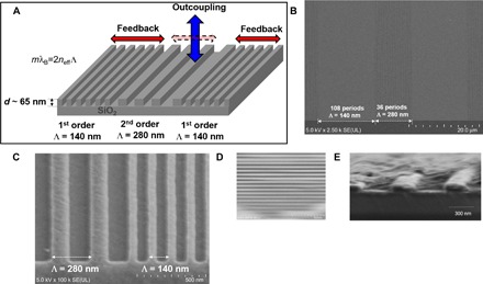
Fig. 2. Structure of the mixed-order DFB resonators.

(A) Schematic representation of the mixed-order DFB grating structure used in this study. SEM images with (B) ×2500 and (C) ×100,000 magnification and (D) SEM image and (E) cross-sectional SEM image of the device after the deposition of a 200-nm-thick BSBCz:CBP blend film.
