
Figure 4.
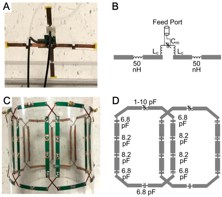
Photographs (A,C) and schematics (B,D) of the crossed dipoles (A,B) which were used as the traveling-wave antenna, and the 8-channel overlapped loop array (C,D) which was used as the passive local coil.
Official websites use .gov
A
.gov website belongs to an official
government organization in the United States.
Secure .gov websites use HTTPS
A lock (
) or https:// means you've safely
connected to the .gov website. Share sensitive
information only on official, secure websites.
Photographs (A,C) and schematics (B,D) of the crossed dipoles (A,B) which were used as the traveling-wave antenna, and the 8-channel overlapped loop array (C,D) which was used as the passive local coil.