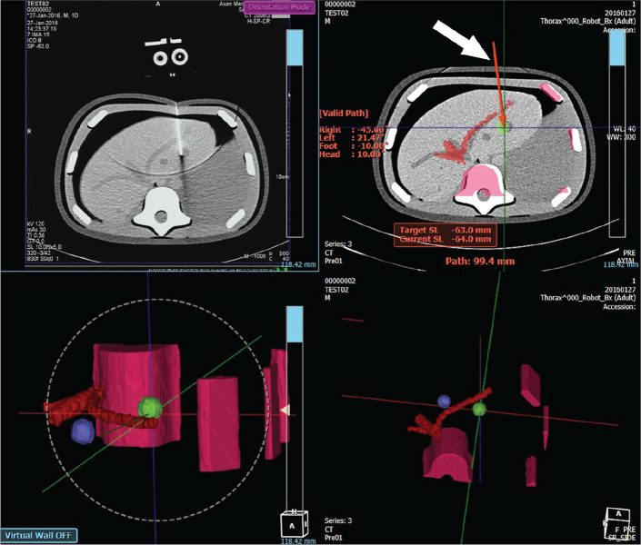
Figure 4.
Screenshot of the path-planning user interface of CT-guided needle placement robot. The top left panel is a CT fluoroscopy image. The top right panel is a planning screen. Solid red line (white arrow) represents the needle path that is located along the viewed slice. It changes to a dotted line when the path crosses two slices or more. The bottom panels are 3D rendering of the planned needle path.

