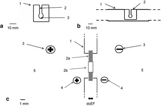
Fig. 1.

Experimental system. a – Electroporation cuvette made from plastic and dialysis membrane. (1) Electroporation cuvette made from plastic. (2) Canal through which cell suspension is inserted into a pocket. (3) Pocket in which the cell suspension is electroporated. Scale bar = 10 mm. b – Electroporation cuvette (2) inserted in the plexiglass barrier (1) in the electrophoresis apparatus. Scale bar = 10 mm. c – Diagram of the experimental setup applied for cell electroporation in an electroporation cuvette in a localized dcEF. (1) Transverse barrier made of plexiglass with a 19-mm diameter gap for inserting the electroporation cuvette with the cell suspension. (2) Electroporation cuvette made from plexiglass (a) and dialysis membrane (b) from Sigma dialysis tubes. (3) Power supply cords with plugs connected to the electrophoresis apparatus. (4) Probe electrodes situated at two sides of the barrier and connected to a voltmeter (Multimeter G-1004.500, RFT) to measure dcEF strength across the barrier. (5) The external solution in which the electroporation cuvette is immersed
