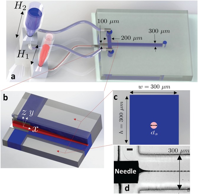
FIG. 1.
The hydrostatic-based microfluidic device. Schematic illustrations show that (a) fluid flow is driven by hydrostatic pressure that is controlled by the liquid column heights and of the sample (red) and sheath (blue) liquids, respectively. The sample flow is supplied to the microchannel via a needle that is inserted into the side of the PDMS slab, and the sheath flow enters the microchannel via tubing connected from the top of the device. (b) Extended isometric sectional view of the flow focusing cross-junction shows that the sheath flow surrounds and flow focuses the sample flow. Sample and sheath fluids both flow in the direction indicated by the x-axis. (c) Cross-sectional view of the microchannel downstream of the cross-junction shows the diameter, ds, of the flow of the sample fluid. (d) Experimental image showing the flow focusing of the sample fluid near the cross junction. The scale bar represents 50 μm.

