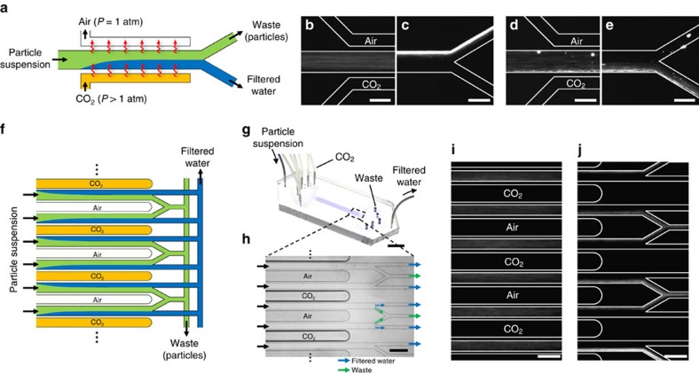
Figure 4. Continuous-flow membraneless water filtration using dissolution of CO2.
(a) Schematic of the water filtration process. The channel material (PDMS) allows permeation of CO2 gas into the particle suspension, inducing directed particle motion normal to the flow direction. (b–e) Fluorescence microscopy images of (b,c) negatively and (d,e) positively charged particles migrating transverse to the flow direction. Images are taken near the (b,d) entrance and (c,e) end of the flow channel, where the channel length is 3 cm. PDMS walls (30 μm wide) separate the parallel gas and flow channels. The CO2 channel is kept at a pressure of 170 kPa whereas the air channel is left open to the atmosphere. The air channel prevents saturation of CO2 in the suspension, thus enhancing particle migration transverse to the flow direction. (f) Schematic of a scalable water filtration process based on the unit device shown in a. (g) Photograph of water filtration device having 10 parallel flow channels in a monolithic PDMS block. (h) Bright-field microscopy image of the microfluidic channels near the outlets. The CO2 channels are kept at 136 kPa whereas the air channels are left open to the atmosphere. (i,j) Fluorescence microscopy images of the negatively charged particles near the (i) entrance and (j) end of the flow channel. The scale bars are (b–e) 100 μm, (g) 1 cm and (h–j) 200 μm.

