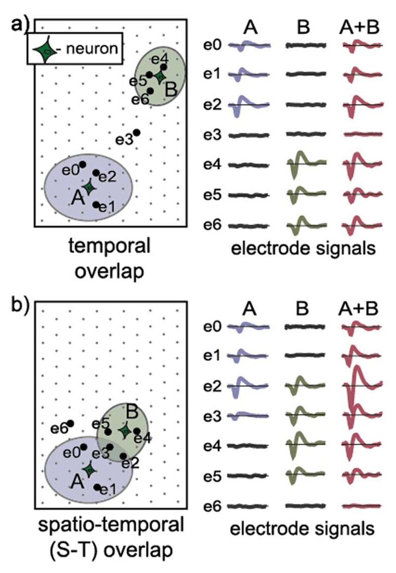
Fig. 1.
Illustration of (a) temporal and (b) spatio-temporal (S-T) spike overlaps. Electrodes able to record spikes from individual neurons are encompassed by ellipsoids. Electrode signals recorded during the individual spiking of neurons A and B are depicted on the right. Electrode signals resulting from simultaneous spiking of two neurons (A + B) represent the sum of the signals recorded during the independent spiking of the neurons. Waveforms used in the plots are simulated spike waveforms, without noise.

