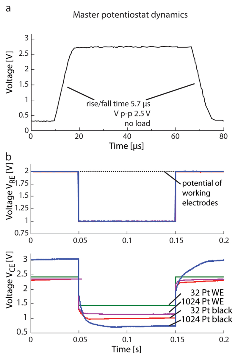
Figure 3.
(a) Step response of the potentiostat without external load showing a slew rate of 350 kV/s. (b top) Voltage at the Ag/AgCl reference electrode for a step of 1 V under different load conditions (solid lines are on top of each other). Dashed line denotes the potential of the working electrodes. (b bottom) Corresponding voltage at the on-chip counter electrode controlled by the potentiostat for a load of 32 blank Pt (green curve), 1024 blank Pt (magenta curve), 32 Pt black (red curve), and 1024 Pt black (blue curve) working electrodes.

