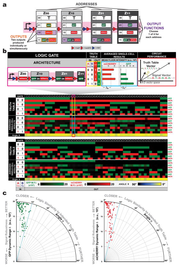
Figure 3. One hundred and thirteen distinct gene circuits with up to two inputs and two outputs implemented using the 2-input BLADE template.
(a) To generate 2-input, 2-ouput circuits, a 2-input BLADE template can be configured with different combinations of output functions: zero-output (transcription termination sequence), one-output (GFP or mCherry) or two-output (GFP-T2A-mCherry). (b) A diverse library of >100 gene circuits, each shown as an individual column with predicted truth table GFP/mCherry ON/OFF behavior (black = no output, green = GFP ON, red = mCherry ON) and corresponding experimental averaged single-cell results obtained from flow cytometry. (c) Angles between each Signal Vector and corresponding Intended Truth Table Vectors are plotted versus worst-case dynamic range values for GFP (δG) and mCherry (δM) signals. Shown above is an expanded view of one of the logic gates made using this platform. M.F.I. = mean fluorescence intensity from n = 3 transfected cell cultures; a.u. = arbitrary units. Error bars represent standard error of the mean.

