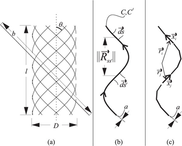
Fig. 2. Braid Model and Neumann Formula.

The braid is modeled as a series of cylindrical helices (a). The length of the curve that makes up each helix is given by b. The angle of this curve with respect to the cylinder axis is given by θ. l and D define the the length and diameter of the cylinder, respectively. The Neumann formula evaluates the relationship between differential elements in the current path. The inductance is calculated using the alignment of the segments and the distance between them. (b) shows a simple, helical current path defined by C made up with differential elements . In the integral form, an identical path C′ is defined. This path is made up with elements . The inner product of the segments is divided by the distance between them. The integral can be evaluated numerically by dividing the path into k segments (c). The length and orientation of the segments is given by and the center point of the segments is given by .
