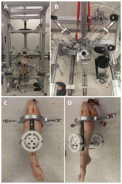
Figure 2.
Depiction of the mechanical impactor simulator. (A) Frontal view of the entire apparatus with a mounted specimen. Pneumatic actuators to apply external load can be seen mounted on the front and side aspects of the simulator structure. (B) Top view of the 6-axis load cell, potting cut, and muscle actuator assembly. The quadriceps actuator is at the inferior aspect of the image while the hamstrings actuators are in the superior corners of the image. (C) Frontal view of the tibial fixture mounted on a specimen. KAM is affixed and applied to the circular rotary elements pictured, while ATS and ITR are affixed to the posts extending medially and laterally from the knee (D) Sagittal view of the tibial fixture mounted on a specimen.

