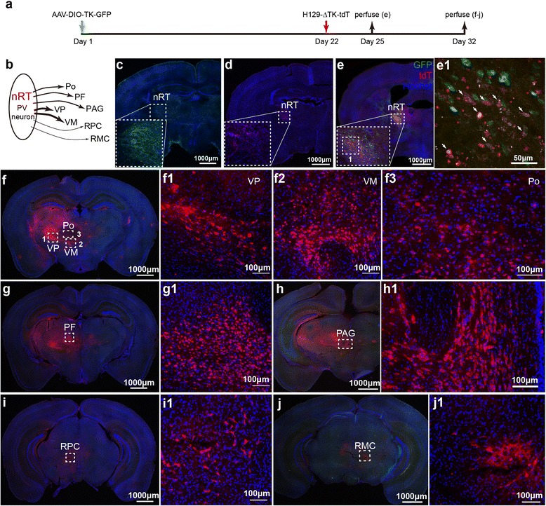
Fig. 5.

Mapping the direct projections from nRT-PV neurons with H129-ΔTK-tdT. a Experiment time line for tracing the VPM pathway with H129-ΔTK-tdT and the helper. b Schema of the direct projections from PV neuron at nRT. PV neuron, parvalbumin neuron; nRT, thalamic reticular nucleus; VP, ventral posterior nucleus; VM, Ventral medial nucleus; Po, posterior thalamic nuclear group; PF, parafascicular thalamic nucleus; PAG, periaqueductal gray; RPC, red nucleus, parvicellular part; RMC, red nucleus, magnocellular part. c–d Controls of the helper and H129-ΔTK-tdT alone. AAV-DIO-TK-GFP (c) or H129-ΔTK-tdT (d) was individually injected into the nRT of PV-Cre mice, and the images were obtained at 21 (c) and 10 dpi (d), respectively. The injection sites are shown with the dotted boxes. (e) The starter neurons of H129-ΔTK-tdT transmission. AAV-DIO-TK-GFP and H129-ΔTK-tdT were injected into nRT of PV-Cre mice at Day 1 and 22 sequentially, and images were obtained at Day 25. The image of the injection site at nRT is shown (e), and the representative region is further magnified (e1). The starter neurons, which express both tdTomato and GFP, are indicated with the white arrows. f–j Tracing the monosynaptic output of nRT-PV neurons. The animals were perfused at Day 32, and the coronal brain slices throughout the entire brains were observed. Shown are the representative images labeled by H129-ΔTK-tdT, including VP, VM, Po (f), PF (g), PAG (h), RPC (i) and RMC (j). Selected regions indicated with dotted boxes are further magnified correspondingly
