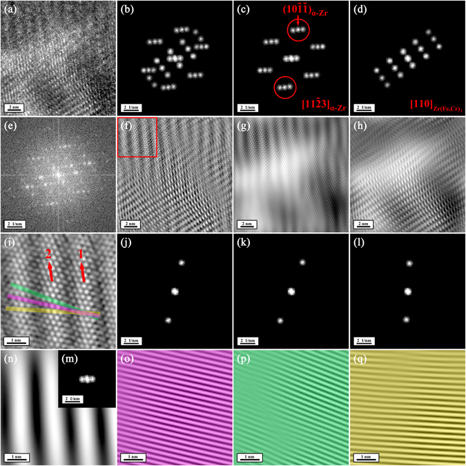
Figure 4.

Moiré fringes at the perimeter of the precipitate of interest. (a) HRTEM image showing an area where fringes disappeared at the interior of the precipitate viewed along the [113]α-Zr direction. (e) The FFT diffraction pattern corresponding to Fig. 4a. (b,c and d) The partially masked FFT diffraction patterns corresponding to Fig. 4c. (f,g and h) The noise-filtered IFFT images corresponding to Fig. 4a obtained by using the partially masked FFT diffraction patterns in Fig. 4(b,c and d), respectively. In Fig. e, b and c, it can be seen that every FFT diffraction spot (including the central FFT diffraction spot) belonging to α-Zr phase along [113]α-Zr diverges into three spots. (i) The expanded morphology of the area outlined by a red square in Fig. 4f. (j,k and l) The three diverged FFT diffraction spots corresponding to the (10)α-Zr planes, respectively. (o,p and q) The IFFT images corresponding to Fig. 4i obtained by using the masked FFT diffraction spots in Fig. 4j, k and l, respectively. (m) The three diverged spots of the central FFT diffraction spot. (n) The IFFT image corresponding to Fig. 4i obtained by using the masked FFT diffraction spots in Fig. 4m. The divergence of the FFT diffraction pattern corresponding to α-Zr phase along [113]α-Zr as well as the central FFT diffraction spot is due to the presence of the fringes. Take the (10)α-Zr planes for example. The (10)α-Zr planes on fringes (pink bar in Fig. 4i) can still form periodic planes (Fig. 4o). The (10)α-Zr planes on Fringe 1 in Fig. 4i can line up with their two adjacent (10)α-Zr planes on Fringe 2 in Fig. 4i (green and yellow bars in Fig. 4i) and form periodic planes (Fig. 4p and q), respectively. In addition, the fringes themselves are periodic, resulting in the divergence of the central FFT diffraction spot as seen in Fig. 4n and m.
