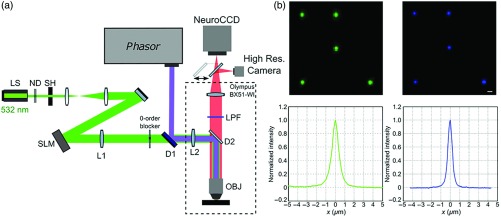
Fig. 1.
Two-color CGH illumination: (a) diagram of the optical setup for holographic illumination patterns at 532 and 405 nm. The 532-nm (green) laser beam from a solid-state laser is attenuated by neutral density filters (ND), enlarged by a telescope, and directed to the liquid crystal SLM. The plane of the SLM is projected with an afocal telescope (L1 and L2) to the back aperture of a microscope objective (OBJ). The 405-nm patterned beam (violet) is generated by a commercial module (phasor) and coupled to the 532-nm beam path thorough a dichroic mirror D1. The patterned beams are reflected toward the objective by the dichroic mirror D2. The collected fluorescence is filtered by the long pass filter (LPF) and directed either to the high-resolution camera or to the high-speed NeuroCCD camera using a movable mirror. (b) Upper panels: Fluorescence pattern generated by a 532-nm (right) and 405-nm (left) digital holography on a thin layer of rhodamine 6G as detected with the NeuroCCD. These patterns were used to calibrate the submicrometric positioning of the holographic spots. Scale bar . Lower panels: spatial profile of the rhodamine emission generated by a 532-nm (green) or 405-nm (blue) CGH spot recorded with the high-resolution camera.

