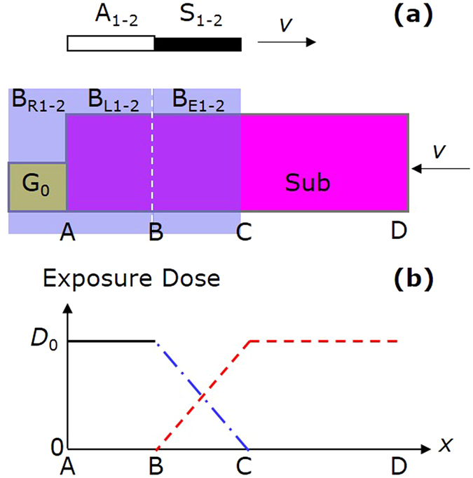
Figure 4.

Linear exposure technique. (a) Exposure procedure. The pink and yellow rectangles denote the substrate and the reference grating G0 respectively. The blue rectangles denote the sub-beams BR1-2, BL1-2, and BE1-2. The gray rectangle denotes the attenuators A1-2. The black rectangle denotes the baffles S1-2. (b) Exposure dose distribution. The black solid, blue dash-dotted, and red dashed lines respectively denote the exposure doses during stationary, linear, and scanning exposures.
