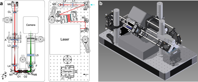
Figure 7.

Optical setup with the Femtolasers Core laser oscillator. (a) Excitation and detection beam paths and the placement of the optical elements on 30 × 60 cm2 breadboard in scale for using the Femtolasers Core laser oscillator. HighQ-2, M-Squared Sprite and CW lasers were coupled into the system by flipping mirror M4 (as shown by the cyan arrow). The xyz coordinate system is indicated as relative to the detection objective, the t-axis represents translation axis. The axis of the cylindrical lens CL is indicated by the dashed line. (b) Computer rendering of the setup. M1–M8 mirrors; DM1, DM2 dispersive mirrors; L1–L5 lenses; CL cylindrical lens; O1 excitation objective; O2 detection objective; F filters; details are given in the Methods and in the Supplementary Table S2.
