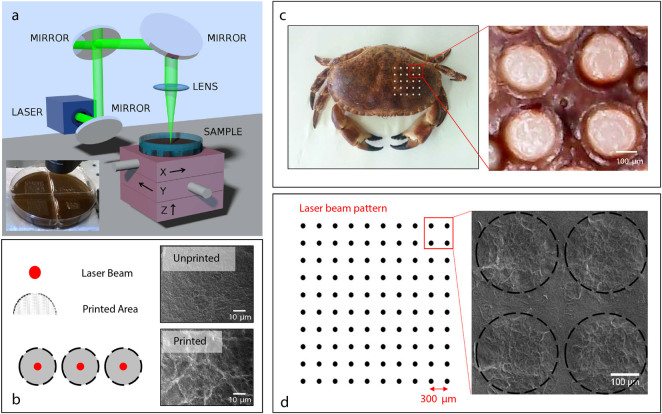
Figure 1.
Pattern realization. (a) Experimental setup for the laser printing of the surface of the Agar substrates. Inset: Patterned GO-agar substrate by focusing a 5 mJ laser pulse. (b) On the left, sketch of the laser pulse action as occurs on the GO-based substrate: the red bullets represent the point interested by the laser pulse, the gray area is subject to the cavitation induced by the thermal expansion of the GO-Agar. The panels on the right show SEM images of the unprinted (top) and printed (bottom) area of the substrate (Figure S1 shows further details). (c) Cancer Pagurus (left) and detail of the carapace pattern (right). (d) Sketch of the geometry of the optically realized patterns (left) and SEM images (right).

