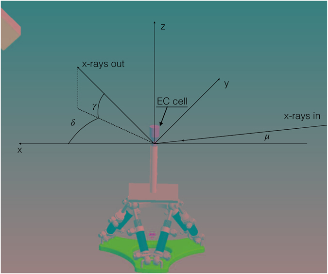
Figure 1.

Schematic layout of the SXRD experiment. In SXRD the reference system is referred to the sample surface with the x- and y-axes laying on the sample surface while the z-axis is perpendicular to it. The x axis is along the projection in the x,y plane of the incident X-ray beam. The hexagonal surface cell of the Ag(111) is used as orientation matrix during the experiment. The a and b vectors are in the the surface plane while the c vector is parallel to the z-axis. In a SXRD experiment the angle of incidence μ is kept at a constant value (1° in our experiment). Once the orientation matrix of the sample is defined a point of the reciprocal space can be reached by moving the gamma, delta and omega angles. The software takes care of calculating the diffractometer angles for any particular scan in the reciprocal space.
