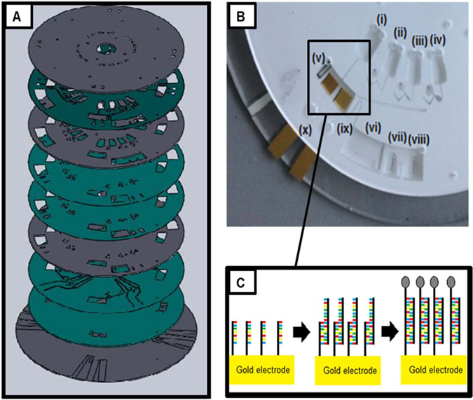
Figure 1.

(A) Detailed view of disc assembly. The grey layers are PMMA, the green layers are PSA. (B) Image of fully assembled disc with integrated electrodes (cropped to view one section). Chamber (i–iv) are preloaded with (i) target miRNA strands, (ii) PBS wash step, (iii) PtNP labelled probe miRNA strands, (iv) PBS wash step/electrolyte. Chamber (v) is the electrode chamber with ITO reference, gold working electrode and gold counter electrode. Chamber (vi) is the waste chamber, with an overflow system implemented at (vii) and (vii); these contain DF tabs. (ix) shows the siphon between the electrode chamber and the waste chamber. Labelled at (x) are the vents for the electrode chamber. (C) Hybridisation of miRNA strands on surface of working electrode inside chamber (v).
