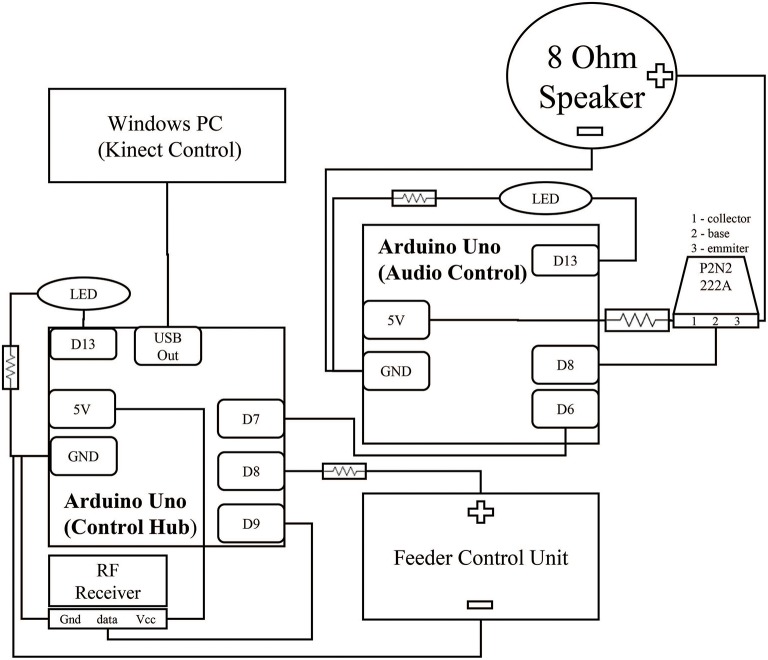
Figure 2.
Circuit for control hub and surrounding components. Two Arduinos control the acquisition of the reward event and the subsequent audio feedback signal. Brown lines represent wiring between components. The black squares within the Arduinos represent individual connections to ports. Digital output ports (Dn) were selected for physical convenience and could be interchanged depending on experiment needs. Both Arduinos contain an LED link to extend the embedded Arduino LED feedback system from PIN 13 to increase visibility from further away. This LED was hidden from the monkey's view during experimentation. All hardware was packaged in a simple cardboard box.

