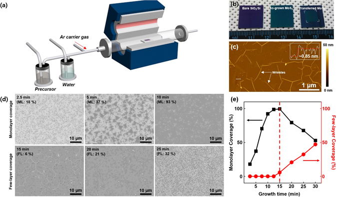
Figure 1.

Synthesis of MoS2 film. (a) Schematic illustration of the CVD system with a liquid precursor and water bubblers. The bubblers are connected with individual mass flow controllers. (b) Photographs of the bare SiO2/Si substrate, as-grown MoS2 film, and transferred MoS2 film. (c) Atomic force microscopy image of the transferred MoS2 film. The inset indicates the height profile along the dotted white line. The white arrows present the MoS2 wrinkles. (d) SEM images of as-grown MoS2 as a function of the growth time. The dark region indicates MoS2, and the white background indicates the SiO2/Si substrate. The coverage for monolayer (ML) and few-layer (FL) MoS2 is displayed in each SEM image. (e) The coverage for monolayer (black) and few-layer (red) MoS2 regions as a function of the growth time.
