
. 2017 Feb 10;4(1):R21–R32. doi: 10.1530/ERP-16-0041
 This work is licensed under a
 Table 2.
Step-wise approach to aortic annular sizing prior to TAVI.
1. Open the 3D analysis software package. The displayed image will be seen in four sections (sagittal, coronal, transverse and a full volume render). Select the mid-systolic frame. Note that the image in the right upper panel is a mirror image: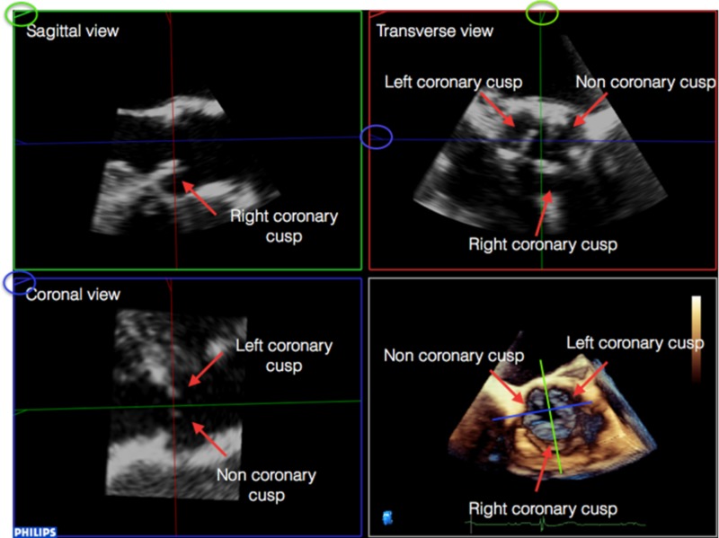
|
2. Align the sagittal and coronal planes to bisect the long-axis of the aortic valve: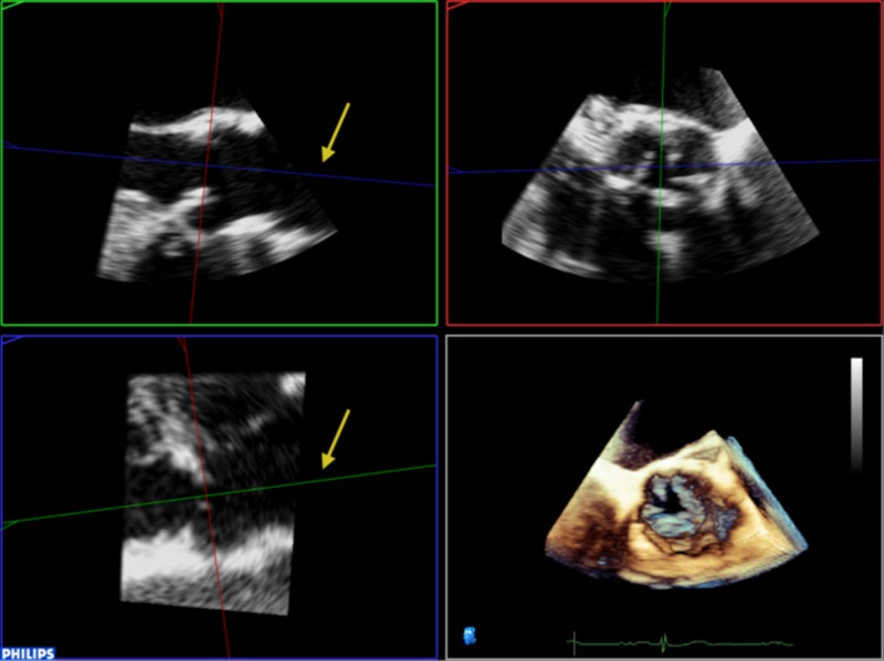
|
3. It is then necessary to align the transverse plane at the level of the annulus, at the most caudal attachment of the three cusps (the hinge point). In this case, the red line representing the transverse view is moved such that it crosses the hinge point of the right coronary cusp in the sagittal view (red arrow) and left (blue arrow) and non-coronary cusp (yellow arrow) in coronal view. By rotating the orthogonal plane of the transverse view, it is important to ensure that the annulus to be measured falls below the hinge points and does not include any caudal aspect of the cusps as this may interfere with accurate measurements: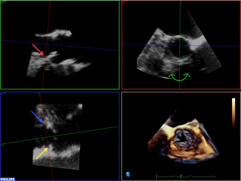
|
4. Rotating the blue plane will help in assuring that the transverse view is bisecting the hinge point at the level of the non and left coronary cusps: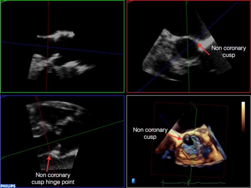 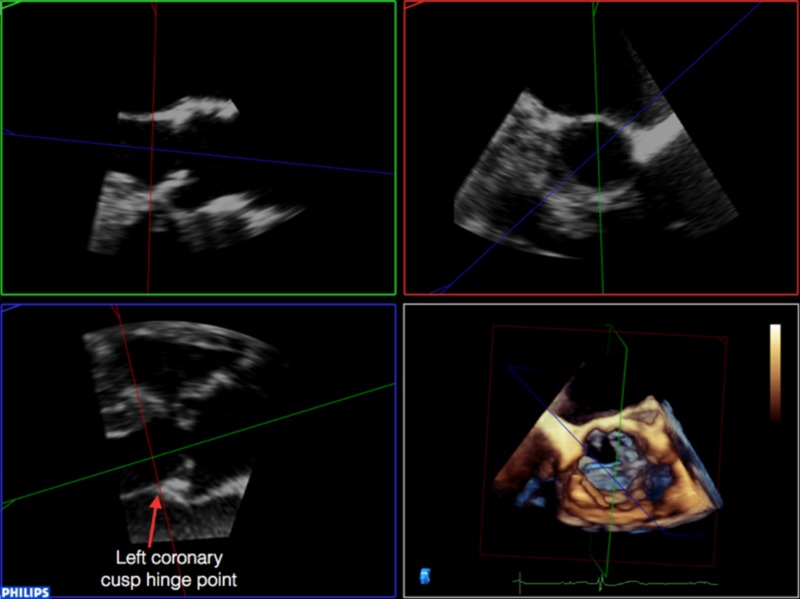
|
5. Select the transverse plane image from this dataset: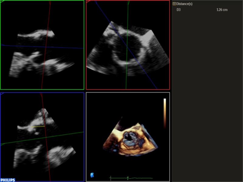
|
| 6. Trace the circumference and area of the annulus by pointing and clicking in an iterative manner around it. This is done in a similar manner to CT, by using the inner edge of the annulus, ignoring any soft low intensity echoes and irregular bright (calcium) indentations, which are traced through. |
7. Once the annulus has been measured, it is possible to identify the ostium of the left main coronary artery and measure the distance between this and the base of the left coronary cusp (any measurement below 11 mm is considered too small to accommodate valve expansion without significant risk of coronary ostial occlusion). Firstly, align the sagittal and coronal planes to bisect the long-axis of the aortic valve. The red marker line on the sagittal plane is then advanced cranially along the aortic root until the origin of the left main stem (LMS) is identified as an indentation at roughly the 10 O’clock position of the transverse image. The green marker of the transvers image is then rotated anti-clockwise until it is aligned with the LMS ostium. The distance from the base of the left coronary cusp to the ostium can then be measured as shown by the yellow marker: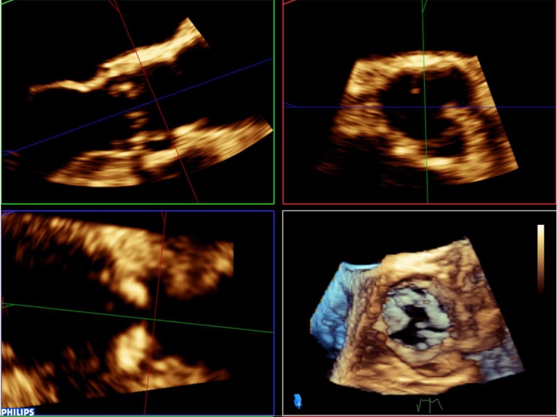 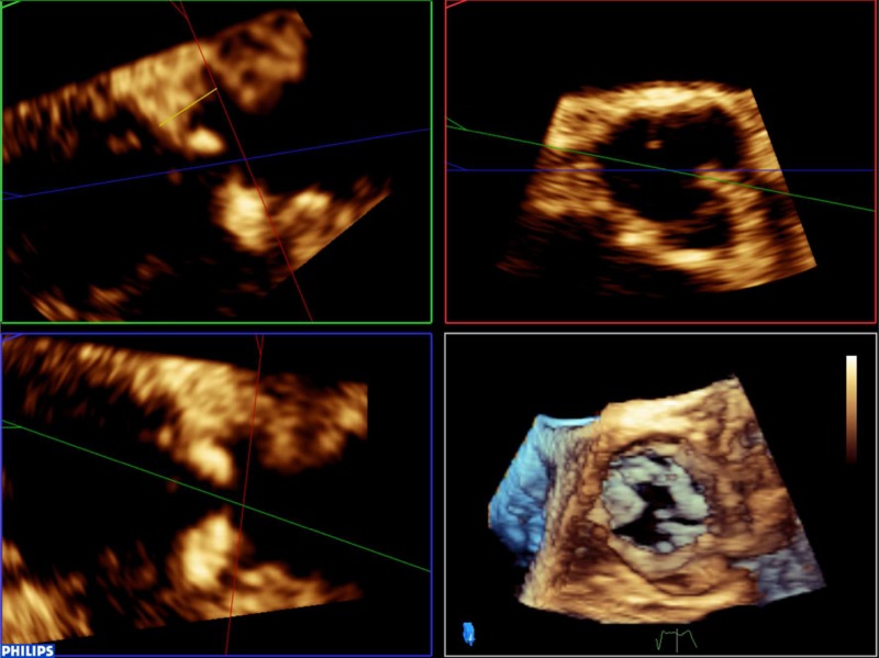
|