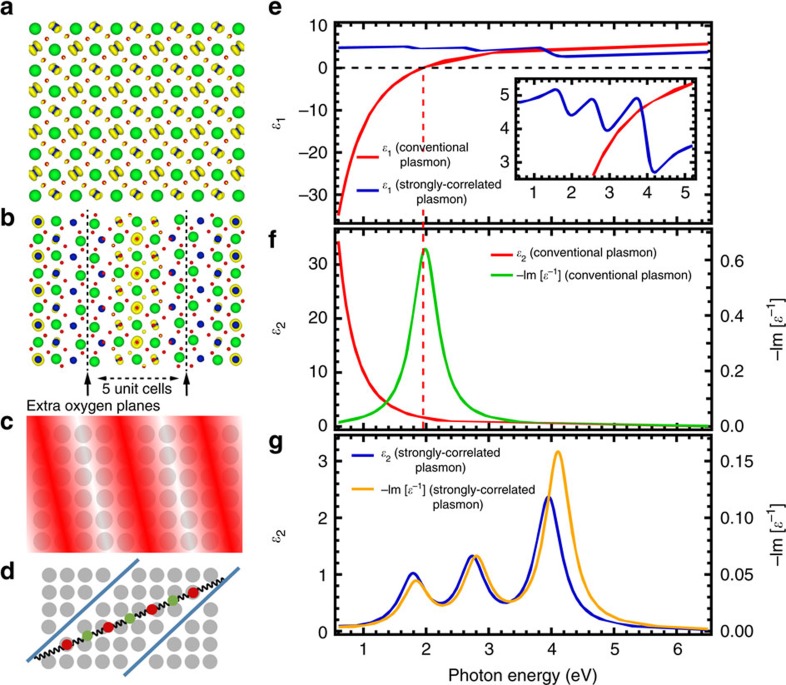
Figure 6. Coupled harmonic oscillator model of correlated plasmons.
(a) Theoretical Nb-4d electron density iso-surface of SrNbO3 superimposed on SrNbO3 crystal structure (Sr=green, Nb=blue, O=red, iso-surface=yellow). (b) Theoretical Nb-4d electron density iso-surface of SrNbO3.4 superimposed on SrNbO3.4 crystal structure. Black dashed lines denote the oxygen walls. The Nb-4d electrons occupy only the middle three Nb planes, while those close to the oxygen walls are depleted of electrons. (c) Illustration of conventional plasmon. Red wave pattern represents the oscillation of free charges, while grey spheres denote the underlying positively charged Nb ionic background. (d) Illustration of coupled harmonic oscillator model of correlated plasmon, showing the case where there are seven oscillators in one chain bounded by two oxygen walls (the coupled seven-oscillator model). Red and green spheres represent the renormalized quasi-electrons coupled by spring-like interaction, while blue lines represent the oxygen walls. (e) Calculated real part of complex dielectric function, ɛ1(ω), of conventional plasmon using Drude model and that of correlated plasmon using coupled seven-oscillator model. Red dashed line indicates the zero-crossing of ɛ1(ω) calculated using Drude model. Inset shows parts of spectra zoomed in for clarity. (f) Calculated imaginary part of complex dielectric function, ɛ2(ω), and loss function, −Im [ɛ−1(ω)], of conventional plasmon using Drude model. (g) Calculated ɛ2(ω) and −Im [ɛ−1(ω)] of correlated plasmon using coupled seven-oscillator model.

