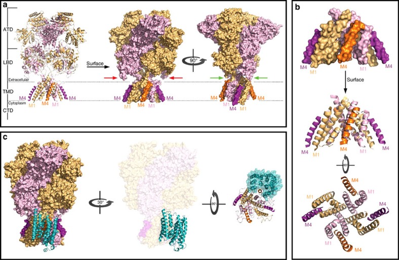
Figure 2. Structural basis for docking of ND2 onto the NMDAR TMD.
(a) Overall architecture of the NMDAR. X-ray crystal structure of the NMDAR (PDB code: 4PE5) in cartoon and surface representations with the GluN1 subunit in light orange and the GluN2 subunit in light purple. Note that the intrinsically disordered CTDs are not shown and the protruding M4 of GluN1 and GluN2 are shown in dark orange and dark purple, respectively. Red arrows show the LBD of GluN2 approaching the membrane, preventing the docking of ND2 to the M4 of GluN2. Green arrows show that there is no such occlusion of GluN1–M4 for docking to ND2. (b) Organization of the TMD of NMDAR. Lateral and cytoplasmic views of the TMD in cartoon and surface representations, colour-coded as in a, revealing how M4 of each subunit lies lateral to the M1 and M3 of the neighbouring subunit. This structural organization results in the protrusion of the M4, and the formation of two shallow grooves between M1 and M4 within one subunit and M4 of one subunit and M1 of the next subunit. (c) Cartoon representation of ND2 (cyan) interacting with the TMD of NMDAR (surface representation colour-coded as in a) in lateral and cytoplasm view. For the sake of clarity, the cytoplasm view of the complex shows only the TMD of the NMDAR (cartoon) and ND2 surface. Note how M4 of GluN1 has very tight surface complementarity to the TM groove of ND2. See also Supplementary Fig. 1.

