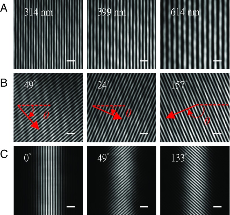
Fig. 3.
Flexible control of interference pattern. For demonstration purposes, the scanning mirrors are tilted to direct the coherent beams into the detection objective lens and thus on the camera. (A) Three images demonstrate the generation of different spatial periods in the illumination pattern by changing the relative angle θx (defined in Fig. 2) of the scanning mirrors. The interference pattern is observable within a certain angular range, i.e., as long as the beams pass both the illumination and detection objective lenses. (B) Three images show the effect of changing the angle θy (defined in Fig. 2) and thus the pattern orientation angles of 49°, 24°, and 157°. (C) Three images show the interference pattern of two light sheets with pattern orientation angles of 0°, 49°, and 133°. The spatial period of the interference pattern is 301 nm. (Scale bars, 1 μm wide.)

