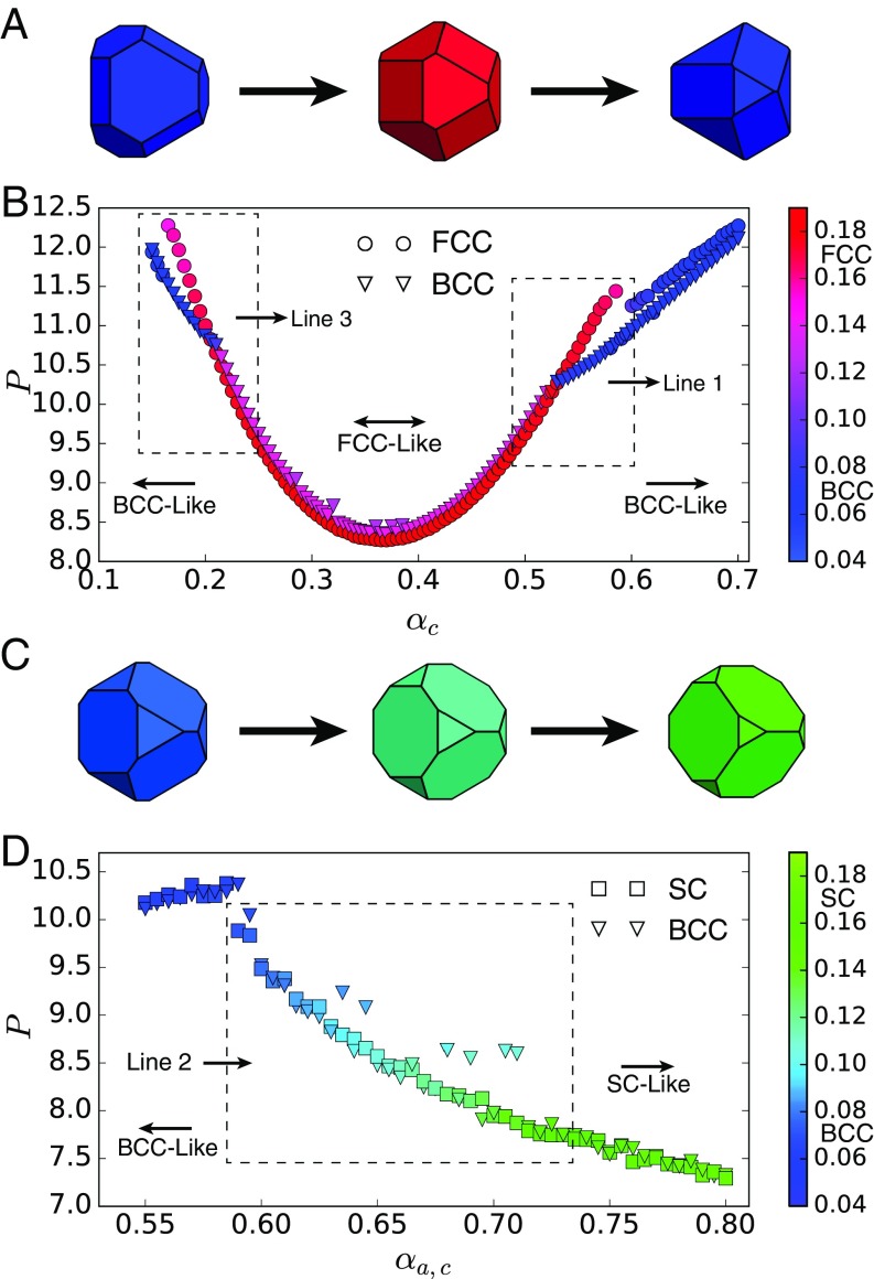
Fig. 3.
Pressure–shape constitutive relation for and . (A) Shape evolution in at fixed . Shapes vary from self-assemble into BCC (blue) to FCC (red) and then back to BCC (blue). (B) Pressure–shape constitutive relation at fixed . Circles indicate FCC system initialization, and triangles indicate BCC system initialization. Marker colors indicate the value of the order parameter computed in the final structure of the system after equilibration. Boxed regions show the BCCFCC boundaries corresponding to lines 1 and 3 in Fig. 1. Errors are smaller than marker size. (C) Shape evolution for . Shapes vary from self-assemble into BCC (blue) to SC (green). (D) Pressure–shape constitutive relation for . Squares indicate SC system initialization; triangles indicate BCC initialization. Marker colors indicate the value of the order parameter computed in the final structure of the system after equilibration. Boxed regions show BCCFCC and BCCSC boundaries corresponding to lines 2, 4, and 5 in Fig. 1. Errors are smaller than marker size. Outliers are systems that did not equilibrate in MC steps.

