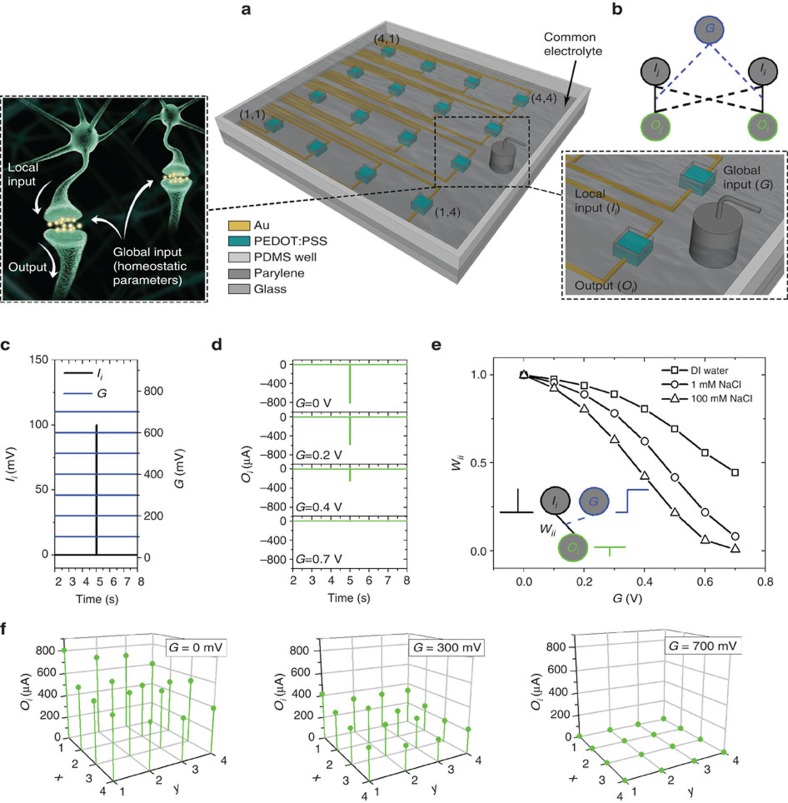
Figure 1. Configuration of the array and principle of global input.
(a) Schematic of the configuration of the array of PEDOT:PSS devices. Each device consists of a PEDOT:PSS channel connected with two Au wires, the local input Ii and the output Oi. The PEDOT:PSS channels are in contact with a common electrolyte in which a Ag/AgCl electrode serves as the global input G. The analogy of the device grid and a system of neurons that are immersed in a common electrolyte is also shown. In neural environment global (homeostatic) parameters regulate the overall function of the brain. (b) Representation of the physical (straight line) and soft connections (dash line) that are established in an array of two devices that are immersed in a common electrolyte. (c) Combinations of local and global inputs (Ii: pulse of amplitude of 100 mV and width of 50 ms, G: DC voltage 0–700 mV), and (d) resulting outputs. (e) Connection weight wii as a function of the global gate voltage G for different electrolyte concentrations (DI water—100 mM NaCl). Inset shows that weight wiiquantifies the physical connectivity between input Ii and output Oi, and that it is modulated by the global input. (f) Spatial maps showing the variation of outputs Oi, when voltages pulses (amplitude of 100 mV, width of 50 ms) were used at each local input Ii, and various DC values (0, 300 and 700 mV) were used as a global input. The Ag/AgCl electrode was located as shown in (b). The maps show that global input forces a global restriction on every output.

