
Figure 4.
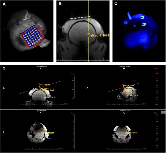
Trajectory alignment. (A): Maximum intensity projection (MIP) of the SmartGrid, a 6 × 6 array of magnetic resonance imaging (MRI)‐sensitive gadolinium‐filled squares placed on the skull covering the estimated entry point of the needle. (B): Three‐dimensional T1‐weighted gradient echo series transferred to the ClearPoint workstation and used to select the target. (C): MIP of the SmartFrame trajectory guide showing fiducial markers used by the software to segment the SmartFrame and to calculate magnetic resonance scanning parameters for planning the trajectory of the cannula. (D): Point of entry and trajectory to the target set based on the anterior and posterior commissures and the midsagittal plane and adjusted, if needed, to ovoid particular structures, ventricular systems, or blood vessels using the “fly‐through” trajectory option. Abbreviations: A, anterior; H, head; L, left.