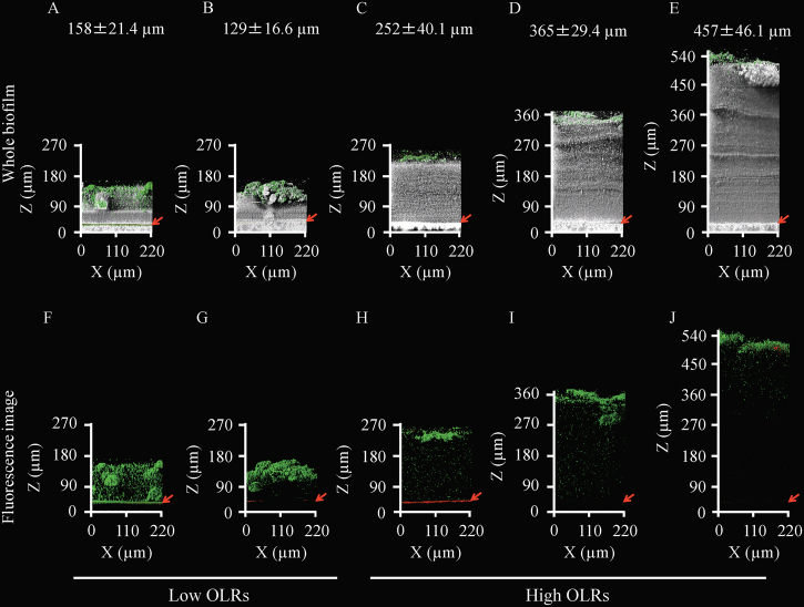
Fig. 1.
Two-dimensional architecture and thickness of fouling-related biofilms. The gray color indicates the physical body reflected by light, the green and red colors indicate live and dead microbial cells, respectively. Live/dead staining was performed with the SYTO9/PI dyes. The red arrows indicate the positions of the membrane surfaces. The average thicknesses of the biofilms are shown in the upper part of the figure. The lower panels show only fluorescent images of the biofilms. The 10 kPa (a, f) and 31 kPa (b, g) TMP biofilms under the low OLR conditions are shown on the left. The six panels on the right show biofilms at 10 kPa (c, h), 30 kPa (d, i), and 50 kPa (e, j) of TMP under the high OLR conditions. At least seven microscopic images were taken per sample, and representative images were shown for presentation. The averages of the biofilm thickness are based on at least three independent determinations, and the standard deviations are indicated

