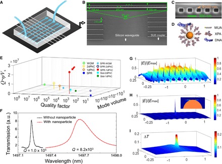
Fig. 1. Photonic-plasmonic hybrid antenna-in-a-nanocavity.

(A) Illustration of the biosensing system, consisting of a silicon photonic chip for biosensing and a polydimethylsiloxane (PDMS) microfluidic chip for sample delivery. (B) Scanning electron microscope image (SEM) of the silicon photonic chip shows the multiplexed photonic crystal nanobeam cavities (zoomed SEM inset) connected by waveguiding components to the edge of the chip for input/output coupling. (C) SEM image of the photonic crystal nanobeam cavity, with a single 50-nm-diameter gold particle located in the central grating of the nanocavity, thus forming an antenna-in-a-nanocavity architecture. (D) Illustration of the biofunctionalized gold nanoparticle. XPA proteins are immobilized to a self-assembled monolayer of 11-mercaptoundecanoic acid (11-MUA) on gold and interact with a double-stranded DNA (dsDNA). (E) Dimensionless factor Qη/ is compared among different microphotonic and nanophotonic systems (for details, see table S1). Solid and hollow circles denote measurements performed in liquid and air, respectively. Our antenna-in-a-nanocavity system is indicated by the red arrow. PhC, photonic crystal cavity; SPR, surface plasmon resonance. (F) Resonance shift of 440 pm and Q-factor drop from 105 to 8.2 × 10³ are the indications of trapping a gold nanoparticle. a.u., arbitrary units. (G) Electromagnetic field distribution of a bare photonic crystal nanobeam cavity without the gold nanoparticle. The cavity mode spans at wavelength cubed scale. (H) Electromagnetic field distribution of the antenna-in-a-nanocavity system. The hybrid mode is strongly localized in the gap region at the nanoparticle-silicon interface. Inset shows the zoomed-in field distribution at the gold nanoparticle (orange hemisphere). (I) Temperature increase distribution. The maximum temperature rise is ~0.2°C under the experimental condition: a power of 5 μW through the silicon waveguide.
