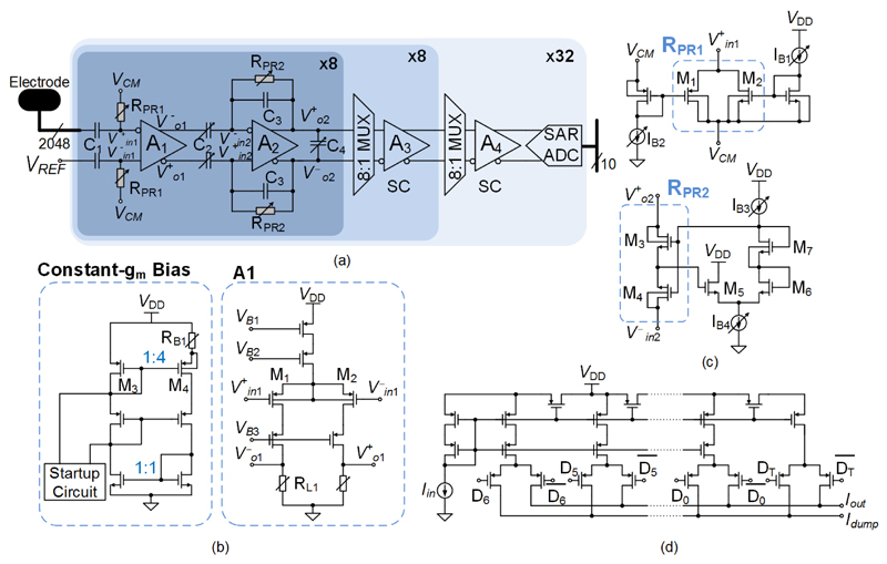
Fig. 4.
AP recording channels. (a) Block diagram of the 2048 AP recording channels. (b) Open-loop amplifier (A1) used in the first stage and its constant-gm bias circuit. (c) Two types of pseudo resistors and their bias circuits. (d) MOSFET-only R-2R current DAC for tuning high-pass corner frequencies.

