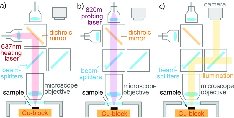
Fig. S1.
The schematic shows the optical paths of the setup. (A) Path of the heating laser. (B) Path of the probing laser. The reflected light traverses the same path before being gathered by a photodetector. (C) Path of camera vision. Cross-polarized picture is obtained by polarizing the incoming illumination and placing an analyzer in front of the camera.

