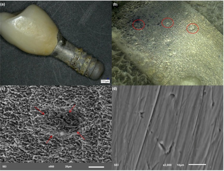
Figure 6.
Structure of implant 5. (a) Low magnification showing the gross features of the implant with bone attachment throughout the surface of the implant and cement surrounding the crown edges; (b) discoloration is also evident in this example; the smooth surface was covered by cement; (c) implant rough interface with evidence of crack development. The arrows highlight a large pit with crack nucleation inside; and (d) higher magnification of an exposed area of the abutment with scratching.

