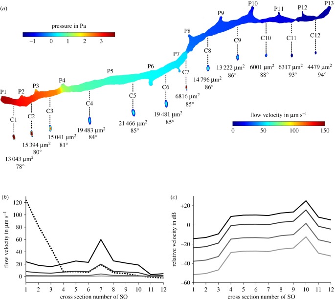
Figure 9.
Simulation of fluid flow inside the right supraorbital canal (SO) of Leuciscus idus. (a) Pressure on the canal walls and fluid flow velocity induced by pressures acting on the canal pores caused by bulk flow and a vibrating sphere. Numbers below the cross sections provide the area of the respective cross section as well as the phase of the sine wave. (b) Average flow velocity of canal fluid measured along the cross sections shown in (a) for DC (dashed line) and sphere displacements of ±150 µm (black), ±50 µm (dark grey), ±10 µm (grey) and ±2 µm (light grey). (c) Relative amplitudes of sphere signal for displacements of ±150 µm (black), ±50 µm (dark grey), ±10 µm (grey) and ±2 µm (light grey) referred to DC flow velocity induced by bulk water flow. C1–C12, canal segment 1–12; P1–P13, canal pore 1–13.

